In the ever-evolving world of 3D coordinate measuring technology, an exciting innovation is emerging that challenges the established methods: "Virtual Clamping".
This approach promises to minimize or even eliminate the need for physical clamping fixtures by relying on virtual simulations. But is virtual clamping really the savior?
What challenges and concerns are associated with this technology? We take a critical look at the pros and cons and examine Duwe-3d AG's expertise in this field to date.
Opportunities and challenges
in the world of measurement of parts
Car front in physical clamping device
Clamping fixture - Tradition
Clamping fixtures are used in the automotive industry, for example, to check unstable components for dimensional accuracy and accuracy of fit and thus ensure their quality.
Purpose and use
-
Quality control: The Meisterbock is used, for example, to ensure that the dimensions of the body parts correspond exactly to the specifications when installed.
-
Assembly planning: It helps with the planning and checking of assembly processes by ensuring that parts can be correctly aligned and assembled.
-
Problem identification: Enables early detection of manufacturing deviations or design problems before mass production begins.
-
Communication tool: Serves as a physical reference point for engineers, technicians and quality management to discuss and visualise discrepancies and modifications.
Virtual Clamping - Innovation
Definition: "Virtual clamping" refers to a technique used in manufacturing, particularly in the automotive industry. Virtual Clamping is an innovative and cost-saving method of fixing components virtually rather than physically during manufacturing or assembly processes. Instead of using traditional clamping or fixturing devices, Virtual Clamping utilises advanced measurement and simulation techniques to ensure the positioning and alignment of parts. For this purpose, FEM (Finite Element Method) software is used to bring the scan data virtually into the state of the installation position.
Purpose and use
-
Increased efficiency: Reduces the need for physical fixtures, which increases flexibility and reduces the time required for conversions and adjustments.
-
Quality assurance: Enables precise measurements and adjustments in real time, resulting in higher product quality.
-
Cost reduction: Saves the cost of manufacturing, maintaining and storing physical fixtures.
-
Digital documentation: Enables comprehensive digital documentation of the assembly process, which is important for quality assurance and traceability.
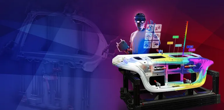
Elimination of physical clamping processes with the help of engineering simulation
Virtually clamped part
Source: VCA Solution by Beta CAE
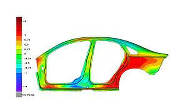
Colour map of CAD and virtually clamped part
Source: VCA Solution by Beta CAE
While a clamping fixture is a physical tool for quality control and assembly planning, virtual clamping is a more technology-driven, flexible approach to increasing efficiency and precision in manufacturing with the help of FEM (finite element method) software. Both concepts play an important role in modern manufacturing processes, especially in areas where precision and quality are critical, such as the automotive industry.
Worries & challanges
Despite the promising nature of virtual clamping, there are some challenges that accompany this technology:
Accuracy of simulations
The accuracy of virtual simulations is at the centre of many discussions. The quality of the measurements depends heavily on the accuracy of the simulations. Errors in the simulation can lead to inaccurate results, which can jeopardise quality assurance.
Resources and training
The successful use of FEM simulation software requires specialised training and access to appropriate resources. Companies must ensure that their employees have the necessary skills to use this technology effectively.
How virtual clamping works in practice
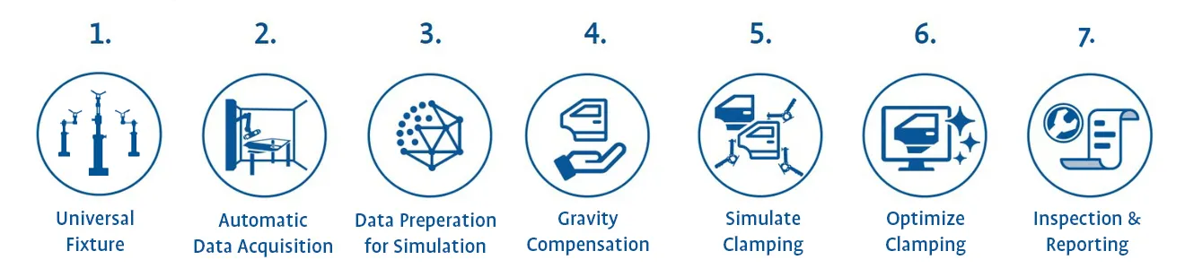
1. Universal Fixture
One of the main tasks of virtual clamping is to eliminate conventional clamping fixtures. Nevertheless, it remains essential to scan and measure the component in a precise and controlled manner. To do this, it is positioned on a flexible scanning device that ensures that each part has at least three defined contact points whose position and shape are known. This flexible scanning device replaces conventional clamping systems. To adapt to different components, the universal clamping fixture must be set up again in each case. PolyWorks helps to position the component optimally so that the universal clamping fixtures can be set precisely.
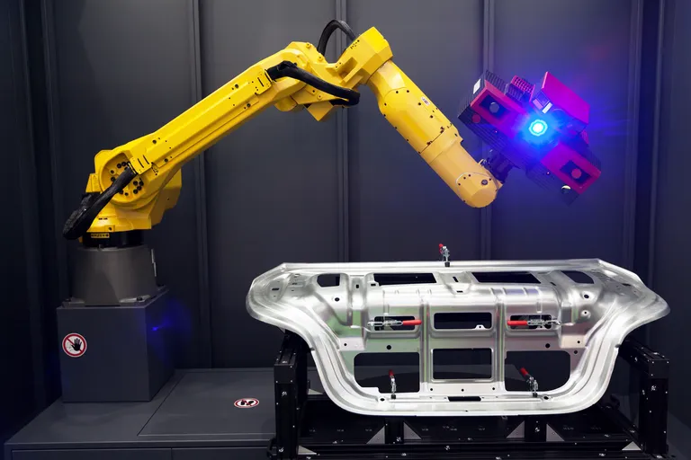
2. Automatic Data Acquisition
The first step is to digitize the sheet metal parts using a custom automated measurement cell. The sheet metal parts will be placed on a flexible scanning fixture in a way that each part will have at least three support points whose position and shape are known. One flexible scanning fixture replaces all previous checking fixtures. PolyWorks interfaces with a variety of robot software and measurement devices so that we will be able to configure the perfect automated measurement cell for Stellantis.
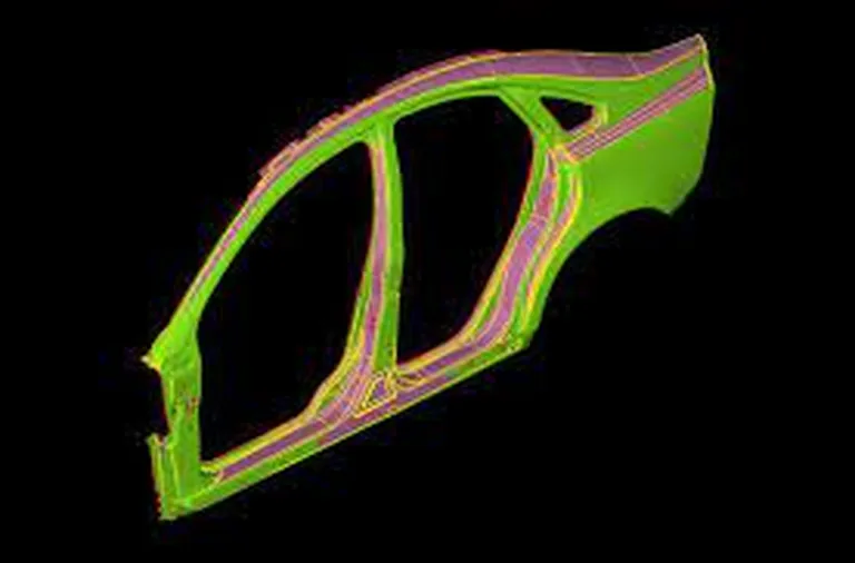
3. Data Preparation for Simulation
Simulation software works better with clean data. The polygonisedscans of the sheet metal must thus be prepared accordingly. This includes e.g.setting scan parameters and point spacing as well as reducing triangles. The edges of the scan are a decisive factor for the accuracy of the result. Inaccurately digitized edges have a strong influence on the clamping simulation. It is necessary to reconstruct clean edges in order tocorrectly simulate the stiffness behavior of the material. Rigid parts and flexible parts will need different data preparation. The data preparation for simulation is automated within PolyWorks.
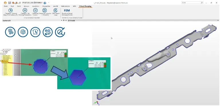
Data preparation for simulation in the FEM software using a special toolbar in PolyWorks
Morphing - an alternative?
Using morphed CAD data instead of the actual scan data can be an alternative under certain circumstances. “Morphing" refers to a process of changing the CAD to resemble the scan dataset. It means moving, stretching and deforming surfaces and curves on the source CAD model so that they match the corresponding points of the target scan model with the goal of maximum congruence. Whether using a morphing engine makes sense must be decided depending on the nature of the parts and the scan quality
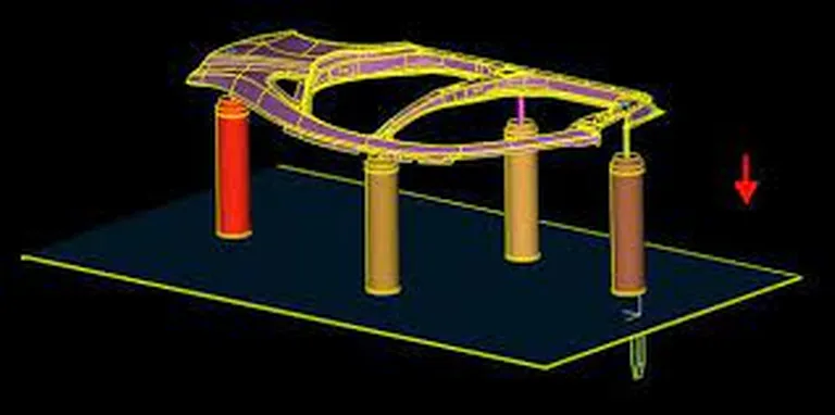
4. Gravity Compensation
The initial scan contains deformation effects caused by gravity, as the sheet-metal part is resting on several supporting points while hanging in the “air” in between those points. For an accurate clamping result these effects need to be factored out first. For this purpose, an FEM engine compensates the gravity effects and puts the scan dataset in a free-floating state. The FEM engine gets information from PolyWorks in order togive back a scan dataset with removed gravity effect:
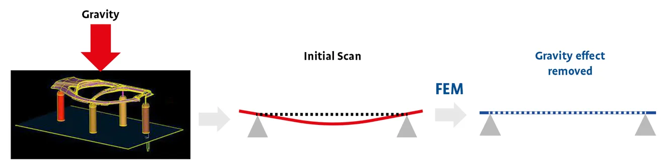
Quelle: Ansa Software by Beta CAE
5. Simulate Clamping
The actual simulation of the clamping process is carried out. The software calculates the reaction of the workpiece to the clamping forces and positions applied. This makes it possible to identify potential problems such as deformation, stress cracks or inadequate fixing of the workpiece. Virtual Clamping eliminates the cost of expensive clamping fixtures that require time-consuming adjustment. Using the right software, such as Hexagon Simufact, Ansa Virtual Clamping software from BETA CAE Systems or software solutions from Autoform, in conjunction with PolyWorks, is crucial to saving costs and time during production. Simulations allow problems to be recognised and rectified in the pre-production phase. This enables an efficient production line and minimises the need for intervention during the production process. While measuring fixtures often also have a certain user influence, a virtual clamping process that has been set up once is very stable and less prone to errors.
Source: Video by Beta CAE shows steps 3-5
6. Optimize Clamping
Based on the simulation results, adjustments are made to optimize the clamping process. This can include fine-tuning the clamping parameters and developing new clamping strategies to improve the efficiency and quality of the manufacturing process.
7. Inspection & reporting
In the last step the virtually clamped scan can be analyzed using the well-known toolset of PolyWorks|Inspector. All proven algorithms and inspection capabilities are at the hand of the user. A seamless transition of data between PolyWorks Users in the metrology lab and the stamping shop is guaranteed with a robust data management solution PolyWorks|DataLoop.
Advantages of virtual clamping
Efficiency in the component creation process
- Component rests on the support points and is freely accessible for measurement
- The result of virtual clamping corresponds to the measurement in an expensive physical fixture
- Less operator influence ensures higher repeat accuracy
- No need to manufacture numerous measuring devices for individual process steps and different components
- Simple change management
- fewer optimization loops required
A look into the future
The future of virtual clamping remains promising, but also challenging. With the increasing accuracy of simulations and the availability of advanced tools, this technology is becoming more and more attractive for companies looking to optimize their measurement processes. The combination of virtual clamping and advanced 3D measurement techniques promises faster, more cost-effective and more accurate quality assurance in the manufacturing industry. Virtual Clamping has the potential to complement or even replace some functions of the traditional master block, especially in the context of digitalization and automation of manufacturing processes
Overall, virtual clamping is an exciting innovation that has the potential to fundamentally change the way we measure and inspect components. Companies should closely follow developments in this area, train their employees accordingly and use the expertise of experienced partners such as Duwe-3d AG to make the most of the many benefits of this technology.
The expertise of Duwe-3d AG
Duwe-3d AG has already established itself as a pioneer in the field of 3D coordinate measuring technology. The company demonstrates its commitment to innovative technologies with virtual clamping pilot projects for well-known automobile manufacturers. Duwe-3d AG's extensive experience and expertise in handling all processes relating to 3D measurement data ensure that virtual clamping is used carefully and effectively, taking into account its advantages and disadvantages.
Together with you, we create a proof of concept and will be happy to advise you on your individual case.
Contact us now
Please advise me on the subject of "Virtual Clamping"